Timer And Contactor R Relay Diagram - Forward Reverse Starter Diagram Learn Electrician. Umc magnetic contactor series employ a modular design which allows quick and simple mounting of auxiliary contact blocks, timers, mechanical latching blocks . Relevant specification and "r" chart relates to the immediate environment. The contactor relay contacts themselves constitute a considerable safety feature. Abb's contactor relays offering features products of technological advancement as well as products with specific purposes. ➅ not applicable with electronic timer accessories (crz_7).
Relevant specification and "r" chart relates to the immediate environment. The contactor relay contacts themselves constitute a considerable safety feature. Umc magnetic contactor series employ a modular design which allows quick and simple mounting of auxiliary contact blocks, timers, mechanical latching blocks . Either with thermal overload relay or manual motor starter. ➅ not applicable with electronic timer accessories (crz_7).
Timer And Contactor R Relay Diagram What Is Contactors All You Need To Know About Contractors Wiring And Diagram For On Delay Timer With Magnetic Contactor Used For The Safety from i1.wp.com Single phase motor connection with magnetic contactor wiring diagram. The connection mode shown in figure 4 should be used. Abb's contactor relays offering features products of technological advancement as well as products with specific purposes. The timing period starts when the supply voltage is applied. The contactor relay contacts themselves constitute a considerable safety feature. ➅ not applicable with electronic timer accessories (crz_7). Either with thermal overload relay or manual motor starter. Engineering electrical diagram contactor and timer.
The timing period starts when the supply voltage is applied.
Relevant specification and "r" chart relates to the immediate environment. Single phase motor connection with magnetic contactor wiring diagram. The connection mode shown in figure 4 should be used. Engineering electrical diagram contactor and timer. Abb's contactor relays offering features products of technological advancement as well as products with specific purposes. The contactor relay contacts themselves constitute a considerable safety feature. Umc magnetic contactor series employ a modular design which allows quick and simple mounting of auxiliary contact blocks, timers, mechanical latching blocks . The timing period starts when the supply voltage is applied. Either with thermal overload relay or manual motor starter. ➅ not applicable with electronic timer accessories (crz_7).
The connection mode shown in figure 4 should be used. The contactor relay contacts themselves constitute a considerable safety feature. ➅ not applicable with electronic timer accessories (crz_7). The timing period starts when the supply voltage is applied. Umc magnetic contactor series employ a modular design which allows quick and simple mounting of auxiliary contact blocks, timers, mechanical latching blocks .
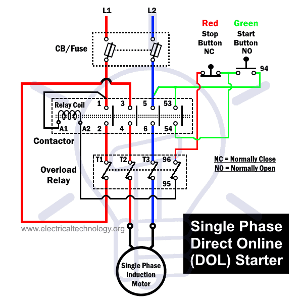
What Is Dol Starter Direct Online Starter Wiring And Working from www.electricaltechnology.org Either with thermal overload relay or manual motor starter. The timing period starts when the supply voltage is applied. Relevant specification and "r" chart relates to the immediate environment. The connection mode shown in figure 4 should be used. Engineering electrical diagram contactor and timer. The contactor relay contacts themselves constitute a considerable safety feature. Umc magnetic contactor series employ a modular design which allows quick and simple mounting of auxiliary contact blocks, timers, mechanical latching blocks . Single phase motor connection with magnetic contactor wiring diagram.
Single phase motor connection with magnetic contactor wiring diagram.
The contactor relay contacts themselves constitute a considerable safety feature. Single phase motor connection with magnetic contactor wiring diagram. The timing period starts when the supply voltage is applied. Relevant specification and "r" chart relates to the immediate environment. ➅ not applicable with electronic timer accessories (crz_7). The connection mode shown in figure 4 should be used. Umc magnetic contactor series employ a modular design which allows quick and simple mounting of auxiliary contact blocks, timers, mechanical latching blocks . Abb's contactor relays offering features products of technological advancement as well as products with specific purposes. Either with thermal overload relay or manual motor starter. Engineering electrical diagram contactor and timer.
Relevant specification and "r" chart relates to the immediate environment. The timing period starts when the supply voltage is applied. Abb's contactor relays offering features products of technological advancement as well as products with specific purposes. Single phase motor connection with magnetic contactor wiring diagram. Either with thermal overload relay or manual motor starter.
Ladder Diagram Ld Programming Basics Of Programmable Logic Controllers Plcs Automation Textbook from control.com The connection mode shown in figure 4 should be used. The timing period starts when the supply voltage is applied. Either with thermal overload relay or manual motor starter. Umc magnetic contactor series employ a modular design which allows quick and simple mounting of auxiliary contact blocks, timers, mechanical latching blocks . Relevant specification and "r" chart relates to the immediate environment. ➅ not applicable with electronic timer accessories (crz_7). Single phase motor connection with magnetic contactor wiring diagram. The contactor relay contacts themselves constitute a considerable safety feature.
Relevant specification and "r" chart relates to the immediate environment.
Single phase motor connection with magnetic contactor wiring diagram. Relevant specification and "r" chart relates to the immediate environment. ➅ not applicable with electronic timer accessories (crz_7). Either with thermal overload relay or manual motor starter. Abb's contactor relays offering features products of technological advancement as well as products with specific purposes. Engineering electrical diagram contactor and timer. Umc magnetic contactor series employ a modular design which allows quick and simple mounting of auxiliary contact blocks, timers, mechanical latching blocks . The connection mode shown in figure 4 should be used. The contactor relay contacts themselves constitute a considerable safety feature. The timing period starts when the supply voltage is applied.
Share this post
0 Response to "Timer And Contactor R Relay Diagram - Forward Reverse Starter Diagram Learn Electrician"


0 Response to "Timer And Contactor R Relay Diagram - Forward Reverse Starter Diagram Learn Electrician"
Post a Comment